


Elementary particles in three dimensions are either bosons or fermions. The existence of only two types is rooted in the fact that the worldlines of two particles in three plus one dimensions can always be untied in a trivial manner. Hence, exchanging a pair of indistinguishable particles twice is topologically equivalent to not exchanging them at all, and the wavefunction must remain the same. Representing the exchange as a matrix R acting on the space of wavefunctions with a constant number of particles, it is thus required that R2 = 1 (a scalar), leaving two possibilities: R = 1 (bosons) and R = −1 (fermions). Such continuous deformation is not possible in two dimensions, thus allowing collective excitations (quasiparticles) to show richer braiding behaviour. In particular, this permits the existence of Abelian anyons2,3,6,7,8,24,25, in which the global phase change due to braiding can take any value. It has been proposed that there exists another class of quasiparticles known as non-Abelian anyons, in which braiding instead results in a change of the observables of the wavefunction4,5,24. In other words, R2 does not simplify to a scalar, but remains a unitary matrix. Therefore, R2 is a fundamental characteristic of anyon braiding. The topological approach to quantum computation26 aims to leverage these non-Abelian anyons and their topological nature to enable gate operations that are protected against local perturbations and decoherence errors5,27,28,29,30. In solid-state systems, primary candidates of non-Abelian quasiparticles are low-energy excitations in Hamiltonian systems, including the 5/2 fractional quantum Hall states31,32, vortices in topological superconductors33,34 and Majorana zero modes in semiconductors proximitized by superconductors35,36,37,38. However, direct verification of non-Abelian exchange statistics has remained elusive39,40,41.
We formulate the necessary requirements for experimentally certifying a physical system as a platform for topological quantum computation5,26: (1) create an anyon pair; (2) verify the rules that govern the ‘collision’ of two anyons, known as the fusion rules; (3) verify the non-Abelian braiding statistics reflected in the matrix structure R2 and (4) realize controlled entanglement of anyonic degrees of freedom. Notably, the observation of steps (2)–(4) requires measurements of multi-anyon states, by means of fusion or non-local measurements.
The advent of quantum processors allows for controlled unitary evolution and direct access to the wavefunction rather than the parameters of the Hamiltonian. These features enable the use of local operations for efficient preparation of topological states that can host non-Abelian anyons, and—as we will demonstrate—their subsequent braiding and fusion. Moreover, these platforms allow for probing arbitrary Pauli strings through destructive multiqubit (that is, non-local) measurements. As the braiding of non-Abelian anyons in this platform is achieved through unitary gate control rather than adiabatic evolution of a Hamiltonian system, we note that the anyons are not quasiparticles in the sense of eigenstates that persist throughout a Hamiltonian evolution. Their movement is achieved through local operations along their paths, and they are kept spatially separated throughout the braiding. We therefore emphasize that the two-dimensional braiding processes are physically taking place on the device, leading to actual non-Abelian exchange effects of local anyons in the many-body wavefunction, rather than matrix operations that simply follow the same algebra.
To realize a many-body quantum state that can host anyons, it is essential to control the topological degeneracy. A suitable platform for achieving this requirement is a stabilizer code42, in which the wavefunctions are characterized by a set of commuting operators ({{hat{S}}_{p}}) called stabilizers, with ({hat{S}}_{p}left|psi rightrangle ={s}_{p}left|psi rightrangle ) and sp = ±1. The code space is the set of degenerate wavefunctions for which sp = 1 for all p. Hence, every independent stabilizer divides the degeneracy of the code space by two.
Whereas the physical layout of qubits is typically used to determine the structure of the stabilizers, the qubits can be considered to be degree j vertices (DjV; j ∈ {2, 3, 4}) on more general planar graphs (Fig. 1a)23. Using this picture, each stabilizer can be associated with a plaquette p, whose vertices are the qubits on which ({hat{S}}_{p}) acts:
$${hat{S}}_{p}=prod _{v,in ,{rm{vertices}}}{hat{tau }}_{p,v}.$$
(1)
({hat{tau }}_{p,v}) is here a single-qubit Pauli operator acting on vertex v, chosen to satisfy a constraint around that vertex (Fig. 1b). An instance where sp = −1 on a plaquette is called a plaquette violation. These can be thought of as quasiparticles, which are created and moved through single-qubit Pauli operators (Fig. 1a). A pair of plaquette violations sharing an edge constitute a fermion, ε. We recently demonstrated the Abelian statistics of such quasiparticles in the surface code43. To realize non-Abelian statistics, one needs to go beyond such plaquette violations; it has been proposed that dislocations in the stabilizer graph—analogous to lattice defects in crystalline solids—can host projective non-Abelian Ising anyons9,10. For brevity, we refer to these as ‘non-Abelian anyons’ or simply ‘anyons’ from here on.
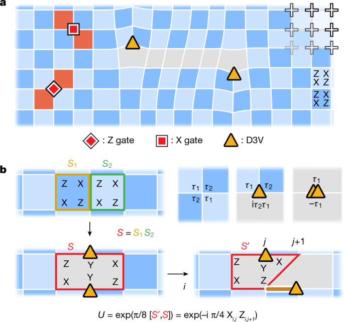
a, Stabilizer codes are conveniently described in a graph framework. Through deformations of the surface code graph, a square grid of qubits (crosses) can be used to realize more generalized graphs. Plaquette violations (red) correspond to stabilizers with sp = −1 and are created by local Pauli operations. In the absence of deformations, plaquette violations are constrained to move on one of the two sublattices of the dual graph in the surface code, hence the two shades of blue. b, A pair of D3Vs (yellow triangles) appears by removing an edge between two neighbouring stabilizers, ({hat{S}}_{1}) and ({hat{S}}_{2}), and introducing the new stabilizer, (hat{S}={hat{S}}_{1}{hat{S}}_{2}). A D3V is moved by applying a two-qubit entangling gate, (exp left(frac{pi }{8}[{hat{S}}^{{prime} },hat{S}]right)). In the presence of bulk D3Vs, there is no consistent way of chequerboard colouring, hence the (arbitrarily chosen) grey regions. The top right shows that in a general stabilizer graph, ({hat{S}}_{p}) can be found from a constraint at each vertex, where {τ1, τ2} = 0.
In the graph framework introduced above, it has been shown that such dislocations are characterized as vertices of degree 2 and 3 (ref. 23). Consider the stabilizer graph of the surface code26,44, specifically with boundary conditions such that the degeneracy is two. Although all the vertices in the bulk are D4Vs, one can create two D3Vs by removing an edge between two neighbouring plaquettes p and q, and introducing the new stabilizer (hat{S}={hat{S}}_{p}{hat{S}}_{q}) (Fig. 1b). Evidently, the introduction of two D3Vs reduces the number of independent stabilizers by one and thus doubles the degeneracy. This doubling is exactly what is expected when a pair of Ising anyons is introduced9,10; hence, D3Vs appear as a candidate of non-Abelian anyons, and we will denote them as σ.
To be braided and fused by unitary operations, the D3Vs must be moved. Whereas the structure of the stabilizer graph is usually considered to be static, it was predicted by Bombin that the dislocations in the surface code would show projective non-Abelian Ising statistics if braided10. Here, we will use a specific protocol recently proposed by Lensky et al.23 for deforming the stabilizer graph (and thus moving the anyons) using local two-qubit Clifford gates. To shift a D3V from vertex u to v, an edge must be disconnected from v and reconnected to u. This can be achieved by means of the gate unitary (exp left(frac{pi }{8}[{hat{S}}_{p}^{{prime} },{hat{S}}_{p}]right)), where ({hat{S}}_{p}) is the original stabilizer containing the edge and u, and ({hat{S}}_{p}^{{prime} }) is the new stabilizer that emerges after moving the edge23. In cases where the D3V is shifted between two connected vertices, the unitary simplifies to the form ({U}_{pm }({hat{tau }}_{u}{hat{tau }}_{v})equiv exp left(pm ifrac{pi }{4}{hat{tau }}_{u}{hat{tau }}_{v}right)), where ({hat{tau }}_{u}) and ({hat{tau }}_{v}) are Pauli operators acting on vertices u and v. We experimentally realize this unitary through a controlled Z (CZ) gate and single-qubit rotations (median errors of 7.3 × 10⁻³ and 1.3 × 10⁻³, respectively; Methods).
Following these insights from Kitaev and Bombin, we now turn to our experimental study of the proposed anyons, using the protocol described in ref. 23. In the first experiment, we demonstrate the creation of anyons and the fundamental fusion rules of σ and ε (Fig. 2a). In a 5 × 5 grid of superconducting qubits, we first use a protocol consisting of four layers of CZ gates to prepare the surface code ground state (Fig. 2b(i), see also ref. 43). The average stabilizer value after the ground state preparation is 0.94 ± 0.04 (individual stabilizer values shown in Extended Data Fig. 3c). We then remove a stabilizer edge to create a pair of D3Vs (σ) and separate them through the application of two-qubit gates. Fig. 2b(i)–(iv) show the measured stabilizer values in the resultant graph in each step of this procedure (determined by simultaneously measuring the involved qubits in their respective bases, n = 10,000; note that the measurements are destructive and the protocol is restarted after each measurement). In Fig. 2b(v), single-qubit Z gates are applied to two qubits near the lower left corner of the grid to create adjacent plaquette violations, which together form a fermion. Through the sequential application of X and Z gates (Fig. 2b(vii)–(viii)), one of the plaquette violations is then made to encircle the right σ vertex. Crucially, after moving around σ, the plaquette violation does not return to where it started, but rather to the location of the other plaquette violation. This enables them to annihilate (Fig. 2b(viii)), causing the fermion to seemingly disappear. However, by bringing the two σ back together and annihilating them (Fig. 2b(ix)–(xi)), we arrive at a striking observation: an ε particle re-emerges on two of the square plaquettes where the σ vertices previously resided.
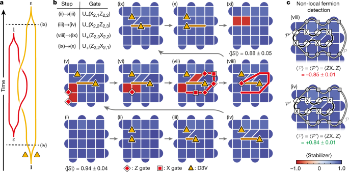
a, The braiding worldlines used to fuse ε and σ. b, Expectation values of stabilizers at each step of the unitary operation after readout correction (see Extended Data Fig. 3 for details and individual stabilizer values). We first prepare the ground state of the surface code (step (i); average stabilizer value of 0.94 ± 0.04, where the uncertainty is one standard deviation). A D3V (σ) pair is then created (ii) and separated (iii)–(iv), before creating a fermion, ε (v). One of the plaquette violations is brought around the right σ (vi)–(viii), allowing it to annihilate with the other plaquette violation (viii). The fermion has seemingly disappeared, but re-emerges when the σ are annihilated ((xi); stabilizer values −0.86 and −0.87). The path (v) → (viii) demonstrates the fusion rule, σ × ε = σ. The different fermion parities at the end of the paths (viii) → (xi) and (iv) → (i) show the other fusion rule, (sigma times sigma ={mathbb{1}}+varepsilon ). Yellow triangles represent the positions of the σ. The brown and red lines denote the paths of the σ and the plaquette violation, respectively. Red squares (diamonds) represent X (Z) gates. Upper left shows a table of two-qubit unitaries used in the protocol. Each stabilizer was measured n = 10,000 times in each step. c, A non-local technique for hidden fermion detection: the presence of a fermion in a σ-pair can be deduced by measuring the sign of the Pauli string (hat{{mathcal{P}}}) corresponding to bringing a plaquette violation around the σ-pair (grey path). (hat{{mathcal{P}}}) is equivalent to the shorter string (hat{{{mathcal{P}}}^{{prime} }}) (black path). Measurements of (hat{{{mathcal{P}}}^{{prime} }}) in steps (viii) (top) and (iv) (bottom) give values of −0.85 ± 0.01 and +0.84 ± 0.01, respectively. This indicates that there is a hidden fermion pair in the former case, but not in the latter, despite the stabilizers being the same.
Our results demonstrate the fusion of ε and σ. The disappearance of the fermion from step (v) to (viii) establishes the fundamental fusion rule of ε and σ:
$$sigma times varepsilon =sigma .$$
(2)
We emphasize that none of the single-qubit gates along the path of the plaquette violation are applied to the qubits hosting the mobile σ; our observations are therefore solely due to the non-local effects of non-Abelian D3Vs, and exemplify the unconventional behaviour of the latter. Moreover, another fusion rule is seen by considering the reverse path (iv) → (i), and comparing it to the path (viii) → (xi). These two paths demonstrate that a pair of σ can fuse to form either vacuum (({mathbb{1}})) or one fermion (steps (i) and (xi), respectively):
$$sigma times sigma ={mathbb{1}}+varepsilon .$$
(3)
The starting points of these two paths ((iv) and (viii)) cannot be distinguished by any local measurement. We therefore introduce a non-local measurement technique that allows for detecting an ε without fusing the σ (refs. 10,23,26). The key idea underlying this method is that bringing a plaquette violation around a fermion should result in a π phase. We therefore measure the Pauli string (hat{{mathcal{P}}}) that corresponds to creating two plaquette violations, bringing one of them around the two σ, and finally annihilating them with each other (grey paths in Fig. 2c). The existence of an ε inside the σ-pair should cause (langle hat{{mathcal{P}}}rangle =-1). To simplify this technique further, (hat{{mathcal{P}}}) can be reduced to a shorter string (hat{{{mathcal{P}}}^{{prime} }}) (black paths in Fig. 2c) by taking advantage of the stabilizers it encompasses. For instance, if (hat{{mathcal{P}}}) contains three of the operators in a four-qubit stabilizer, these can be switched out with the remaining operator. Measuring (langle hat{{{mathcal{P}}}^{{prime} }}rangle ) in step (iv), in which the σ are separated but the fermion has not yet been introduced, gives (langle hat{{{mathcal{P}}}^{{prime} }}rangle =+,0.84pm 0.01), consistent with the absence of fermions (Fig. 2c). However, performing the exact same measurement in step (viii), in which the σ are in the same positions, we find (langle hat{{{mathcal{P}}}^{{prime} }}rangle =-,0.85pm 0.01), indicating that an ε is delocalized across the spatially separated σ pair (Fig. 2c). This observation highlights the non-local encoding of the fermions, which cannot be explained with classical physics.
Having demonstrated the above fusion rules involving σ, we next braid them with each other to directly show their non-Abelian statistics. We consider two spatially separated σ pairs, A and B, by removing two stabilizer edges (Fig. 3a,b(ii)). Next, we apply two-qubit gates along a horizontal path to separate the σ in pair A (Fig. 3b(iii)), followed by a similar procedure in the vertical direction on pair B (Fig. 3b(iv)), so that one of its σ crosses the path of pair A. We then subsequently bring the σ from pairs A and B back to their original positions (Fig. 3b(v)–(viii) and (ix)–(xi), respectively). When the two σ pairs are annihilated in the final step (Fig. 3b(xii)), we observe that a fermion is revealed in each of the positions where the σ pairs resided (average stabilizer value −0.45 ± 0.06). This shows a clear change in local observables from the initial state in which no fermions were present. As a control experiment, we repeat the experiment with distinguishable σ pairs, achieved by attaching a plaquette violation to each of the σ in pair B (Fig. 3c,d; see also Extended Data Fig. 8 for stabilizer measurements through the full protocol). Moving the plaquette violation along with the σ requires a string of single-qubit gates, which switches the direction of the rotation in the multiqubit unitaries, U± → U∓. In this case, no fermions are observed at the end of the protocol (average stabilizer value +0.46 ± 0.04), thus providing a successful control.
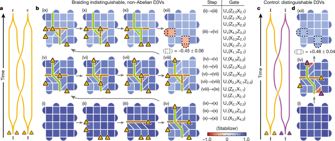
a, Wordline schematic of the braiding process. b, Experimental demonstration of braiding, showing the values of the stabilizers throughout the process. Two σ pairs, A and B, are created from the vacuum ({mathbb{1}}), and one of the σ in pair A is brought to the right side of the grid. Next, a σ from pair B is moved to the top, thus crossing the path of pair A, before bringing σ pairs A and B back together to complete the braid. In the final step, two fermions appear in the locations where the σ pairs resided, constituting a change in the local observables. The diagonal σ move in step (iv) requires two SWAP gates (three CZ gates each) and a total of ten CZ gates. The three-qubit unitary in step (viii) requires four SWAP gates and a total of 15 CZ gates. In the full circuit, a total of 40 layers of CZ gates are applied (Methods). The yellow triangles represent the locations of the σ; the brown and green lines represent the paths of σ from pairs A and B, respectively. The four red stabilizers in (xii) have a mean value of −0.45 ± 0.06, where the uncertainty is one standard deviation. Each stabilizer was measured n = 10,000 times in each step. c, As a control experiment, we perform the same braid as in a, but with distinguishable σ by attaching a plaquette violation to the σ in pair B (represented with purple triangles). d, Same as b, but using distinguishable σ (only showing steps (i), (iv) and (xii)). In contrast to b, no fermions are observed in step (xii).
Fermions can only be created in pairs in the bulk. Moreover, the fusion of two σ can only create zero or one fermion (equation (3)). Hence, our experiment involves the minimal number of bulk σ (four) needed to encode two fermions and demonstrate non-Abelian braiding. Because the fermion parity is conserved, effects of gate imperfections and decoherence can be partially mitigated by postselecting for an even number of fermions. This results in fermion detection values of −0.76 ± 0.03 and +0.79 ± 0.04 in Fig. 3b,d, respectively.
Together, our observations show the change in local observables by braiding of indistinguishable σ and constitute a direct demonstration of their non-Abelian statistics. In other words, the double-braiding operation R2 is a matrix that cannot be reduced to a scalar. Specifically, it corresponds to an X gate acting on the space spanned by zero- and two-fermion wavefunctions.
The full braiding circuit consists of 40 layers of CZ gates and 41 layers of single-qubit gates (36 of each after ground state preparation). The effects of imperfections in this hardware implementation can be assessed through comparison with the control experiment. The absolute values of the stabilizers in which the fermions are detected in the two experiments (dashed boxes in Fig. 3b,d(xii)) are very similar (average values of −0.45 and +0.46). This is consistent with the depolarization channel model, in which the measured stabilizer values are proportional to the ideal values (±1).
We next study the prospects of using D3Vs to encode logical qubits and prepare an entangled state of anyon pairs. By doubling the degeneracy, each additional σ pair introduces one logical qubit, where the ({left|0rightrangle }_{{rm{L}}}) (({| 1rangle }_{{rm{L}}})) state corresponds to an even (odd) number of hidden fermions. The measurements of the fermion numbers in several σ pairs are not fully independent: bringing a plaquette violation around one σ pair is equivalent to bringing it around all the other pairs (due to the conservation of fermionic parity). Hence, N ≥ 2 anyons encode N/2 − 1 logical qubits. The D3Vs we have created and manipulated so far are not the only ones present in the stabilizer graph; with the boundary conditions used here, each of the four corners are also D3Vs, no different from those in the bulk23. Indeed, the existence of D3Vs in the corners is the reason why a single fermion could be created in the corner in Fig. 2b(v). This is also consistent with the fact that the surface code itself encodes one logical qubit in the absence of additional D3Vs. Here we create two pairs of D3Vs, in addition to the four that are already present in the corners, to encode a total of three logical qubits.
Through the use of braiding, we aim to prepare an entangled state of these logical qubits, specifically a GHZ state on the form ((| 000rangle +| 111rangle )/sqrt{2}). The definition of a GHZ state and the specifics of how it is prepared is basis-dependent. In most systems, the degrees of freedom are local and there is a natural choice of basis. For spatially separated anyons, the measurement operators are necessarily non-local. Here we choose the basis defined as follows: for the first two logical qubits, we choose the logical ({hat{Z}}_{{rm{L}},i}) operators to be Pauli strings encircling each of the bulk σ pairs, as was used in Fig. 2c (green and turquoise paths in the left column of Fig. 4a). For the logical surface code qubit, we define ({hat{Z}}_{{rm{L}},3}) as the Pauli string that crosses the grid horizontally through the gap between the bulk D3V pairs, effectively enclosing four σ (red path in Fig. 4a). In this basis, the initial state is a product state.
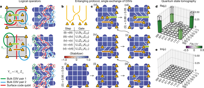
a, Logical operators of the three logical qubits encoded in the eight anyons (other basis choices are possible). The coloured curves in the left column denote plaquette violation paths, before reduction to shorter, equivalent Pauli strings measured in the experiment (right column). b, Worldline schematic of the single exchange used to realize an entangled state of the logical qubits. c, Single exchange of the non-Abelian anyons, showing measurements of the stabilizers throughout the protocol. Yellow triangles represent the locations of the σ, whereas brown and green lines denote their paths. The average stabilizer values are 0.95 ± 0.04 and 0.88 ± 0.05 (one standard deviation) in the first and last step, respectively. Each stabilizer was measured n = 20,000 times in each step. d,e, Real (d) and imaginary (e) parts of the reconstructed density matrix from the quantum state tomography. ({rm{Re}}(rho )) has clear peaks in its corners, as expected for a GHZ state on the form ((left|000rightrangle +left|111rightrangle )/sqrt{2}). The overlap with the ideal GHZ state is ({rm{Tr}}{,{rho }_{{rm{GHZ}}}rho }=0.623pm 0.004), where the uncertainty is one standard deviation determined from bootstrapping.
Whereas a double braid was used to implement the operator X in Fig. 3, we now perform a single braid (Fig. 4b) to realize (sqrt{X}) and create a GHZ state. We implement this protocol by bringing one σ from each bulk pair across the grid to the other side (Fig. 4c). For every anyon double exchange across a Pauli string, the value of the Pauli string changes sign. Hence, a double exchange would change (left|000rightrangle ) to (left|111rightrangle ), whereas a single exchange is expected to realize the superposition, ((left|111rightrangle +left|000rightrangle )/sqrt{2}).
To study the effect of this operation, we perform quantum state tomography on the final state, which requires measurements of not only ({hat{Z}}_{{rm{L}},i}), but also ({hat{X}}_{{rm{L}},i}) and ({hat{Y}}_{{rm{L}},i}) on the three logical qubits. For the first two logical qubits, ({hat{X}}_{{rm{L}},i}) is the Pauli string that corresponds to bringing a plaquette violation around only one of the σ in the pair (as demonstrated in Fig. 2b). Both the logical ({hat{X}}_{{rm{L}},i}) and ({hat{Z}}_{{rm{L}},i}) operators can be simplified by reducing the original Pauli strings (green and turquoise paths in the left column of Fig. 4c) to equivalent, shorter ones (right column). ({hat{Z}}_{{rm{L}},1}) can in fact be reduced to a single (hat{Y})-operator. For the logical surface code qubit, we define ({hat{X}}_{{rm{L}},3}) as the Pauli string that crosses the grid vertically between the bulk D3V pairs (red path in Fig. 4a). Finally, the logical ({hat{Y}}_{{rm{L}},i})-operators are simply found from ({hat{Y}}_{{rm{L}},i}=i{hat{X}}_{{rm{L}},i}{hat{Z}}_{{rm{L}},i}). Measuring these operators, we reconstruct the density matrix of the final state (Fig. 4d,e), which has a purity of (sqrt{{rm{Tr}}{{rho }^{2}}}=0.646pm 0.003) and an overlap with the ideal GHZ state of ({rm{Tr}}{{rho }_{{rm{GHZ}}}rho }=0.623pm 0.004) (uncertainties estimated from bootstrapping method; resampled 10,000 times from the original data set). The fact that the state fidelity is similar to the purity suggests that the infidelity is well described by a depolarizing error channel.
In conclusion, we have realized highly controllable braiding of degree-3 vertices, enabling the demonstration of the fusion and braiding rules of non-Abelian Ising anyons. We have also shown that braiding can be used to create an entangled state of three logical qubits encoded in these anyons. In other, more conventional candidate platforms for non-Abelian exchange statistics, which involve Hamiltonian dynamics of quasi-particle excitations, topological protection naturally arises from an emergent gap that separates the computational states from other states. To leverage the non-Abelian anyons in our system for topologically protected quantum computing, the stabilizers must be measured throughout the braiding protocol. The potential inclusion of this error correction procedure, which involves overheads including readout of five-qubit stabilizers, could open a new path towards fault-tolerant implementation of Clifford gates, a key ingredient of universal quantum computation.
More News
AI & robotics briefing: AI decodes languages in first ‘bilingual’ brain-reading device
Mexico’s next president is likely to be this scientist — but researchers are split in their support
Pro-CRISPR PcrIIC1-associated Cas9 system for enhanced bacterial immunity – Nature